martes, 4 de marzo de 2014

The Clothoid - Properties - Propiedades


The Clothoid, also known as ”Spiral of Cornú” or ”Spiral of Euler”, is a curve with features that makes it ideal to design transition curves.

The mist valuable feature for us is that from the point that is tangent to the straight-line (Start of Transition curve or P.C.T.), its curvature 1/R starts to increase linearly subject to its development until it reaches the circle-arc at the End of Transition Curve (F.C.T.).
L = Total Length of the clothoid
R = Radius of the circular curve
j= Angle in the point of tangency with the circular-curve 
P.C.T. = Start of Transition Curve
F.C.T. = End of Transition Curve
Parameter of the Clothoid   A=SQR(L x R)


Coordinates of the point P(x,y)
P(x,y)= Any point of the Clothoid
lx * rx = L * R = constant
rx = Radius in a point P(x,y) 
lx =Distance from P.C.T.  to point P
j= L / (2 * R) :        Total angle of the Clothoid
jx= (lx2) / (2 * L* R) : Angle in the point P
X=(lx*(1-((1/40)*((2*jx)2))+((1/3456)*((2*jx)4))-((1/336960)*((2*jx)6))+((1/43868160)*((2*jx)8))))
Y=(lx*(jx/3)*(1-((1/56)*((2*jx)2))+((1/7040)*((2*jx)4))-((1/453600)*((2*jx)6))+((1/73543680)*((2*jx)8))))

Despite the development of these formulae is infinite, with the terms exposed the accuracy is more than enough in order to know the exact situation of each point of the Clothoid with regards to the P.C.T.


GO TO CHAPTER VI - Straightening of Railway Curves

Full themes in the book -In paper and ebook -(Follow the link)


----------------------------------------------------


PROPIEDADES DE LA CLOTOIDE

La Clotoide se conoce también como ”espiral de Cornú” o ”espiral de Euler”, es una curva cuyas características la hace ideal para trazar las curvas de transición.ž

Su principal característica es que a partir del punto en el que es tangente a la recta (P.C.T.), su curvatura (1/R) comienza a aumentar linealmente en función de su desarrollo hasta alcanzar el arco de circulo (F.C.T.)
L = Longitud total de la clotoide
R = Radio de la circular

j= Ángulo en el punto de tangencia con la circular
P(X,Y)= Un punto de la clotoide.
P.C.T. = Principio Curva Transición
F.C.T. = Final Curva Transición

Parámetro de la clotoide   A=Raiz(L x R)

Coordenadas de un punto (P(x,y)


P(x,y)  es un punto cualquiera de la clotoide
lx * rx = L * R = constante
rx = Radio en un punto P(x,y)
lx =Distancia del P.C.T. al punto P

j= L / (2 * R) : Ángulo total de la Clotoide
jx= (lx ^ 2) / (2 * L* R) : Ángulo en un punto P

X=(lx*(1-((1/40)*((2*jx)2))+((1/3456)*((2*jx)4))-((1/336960)*((2*jx)6))+((1/43868160)*((2*jx)8))))
Y=(lx*(jx/3)*(1-((1/56)*((2*jx)2))+((1/7040)*((2*jx)4))-((1/453600)*((2*jx)6))+((1/73543680)*((2*jx)8))))

Aunque el desarrollo de estas fórmulas es infinito, con los términos expuestos, la precisión es más que suficiente para conocer la situación exacta de cualquier punto de la clotoide respecto al PCT.


IR A CAPÍTULO VI - Rectificación de Curvas Ferroviarias

Temas completos en el libro - en papel y ebook (Siga este enlace)


The Clothoid - La Clotoide


INDEX 


GO TO CHAPTER V- Properties of the Clothoid

Full themes in the book -In paper and ebook-(Follow the link)


------------------------------------------------------

INDICE
  • Representación de las curvas
    • Diagrama de curvaturas 
    • Diagrama de flechas 
    • Diagrama de ángulos 

IR A CAPÍTULO V - Propiedades de la Clotoide

Temas completos en el libro - en papel y ebook - (Siga este enlace)


lunes, 3 de marzo de 2014

The Camber in the Railway - Pendular Trains - Trenes pendulares


Currently there exist a type of train called “pendular trains”, as is the case of the Pendular Talgo and the Pendolino. This trains are specials and the previous formulae for the camber do not apply. 

When a train enters a curve at a speed higher than the one corresponding to a non-compensated acceleration of 0,65 m/s2, the people inside the vehicle experiment the effect of the centrifugal force, being displaced outwards. 

A pendular train, however, is tilted towards the interior of the curve at an angle that exceeds the tilted plane of the camber, which counteracts the non-compensated acceleration excess and allows the train to pass the curves at higher speeds than common trains.


There exist pendular or passive trains, which are tilted by the inertia of the curve as a pendule does, and also “swingers” or active, which are equipped with automatic devices to tilt the train.


Sistema basculante (Pendolino)

A pendular train of type “D” of Renfe (the one which compensates more acceleration: 1,8 m/s²) can pass a curve of 300m radius and camber of 160 mm at 103 km/h

V= 5.92 * SQR( R ).

Without swinging, this speed would cause a non-compensated acceleration of 2,45 ms².

These trains circulate with the same comfort as a type N at 78 km/h and anc=0,65 m/s².

V=4,48 * SQR( R ).


---------------------------------------------------------------


TRENES PENDULARES
Actualmente en el mundo circulan los llamados trenes pendulares como es el caso del "Talgo pendular" y el "Pendolino" , estos trenes son especiales y las fórmulas anteriores no se les aplica.


Cuando un tren toma una curva a mayor velocidad que la que correspondería para una aceleración sin compensar de 0,65 m/s2, las personas en su interior, experimentan el efecto de la fuerza centrífuga, tendiendo a desplazarse hacia el exterior. 

Un tren pendular se inclina hacia el interior de la curva un ángulo que supera el plano inclinado del peralte , lo que contrarresta ese exceso de aceleración sin compensar y le permite tomar las curvas a mayor velocidad que los trenes normales.


Existen los trenes pendulares o pasivos, que se inclinan por la inercia de la curva como se inclina un péndulo, y los basculantes o activos, que disponen de mecanismos automáticos que inclinan el tren.


Sistema basculante (Pendolino)


Así, un tren Tipo D de Renfe (el que más compensa: 1,8 m/s²) puede pasar una curva de 300 m de radio (con peralte de 160 mm) a 103 km/h

V= 5.92 * Raiz( R ).

Sin basculación provocaría una aceleración lateral no compensada de 2,45 ms².

Y estos trenes circulan con el mismo confort que un Tipo N a 78 km/h y anc=0,65 m/s².

V=4,48 * Raiz( R ).

The Camber in the Railway - El Peralte en el Ferrocarril


INDEX

  • Constants
  • Theory of the camber 
    • General concepts 
    • Application to railways 
      • Theoretical camber 
      • The circulation in curves 
      • Acceleration without compensation 
      • Speed subject to radius and camber 
      • Minimum radius 
      • Excess of camber 
      • Formula of the camber 
      • Formula of camber lack 
  • Camber in transition curves 
    • Length of transition curves 
      • Over-acceleration 
      • Track twist 
      • Ramp of maximum camber 
      • Vertical or turn-acceleration 
  • Pendular trains 

GO TO CHAPTER III- The Camber in the Railroad- Constans

Full themes in the book -In paper and ebook-(Follow the link)


-----------------------------------------------------------


INDICE
  • Teoría del peralte
    • Conceptos generales
    • Aplicación a la vías férreas
      • Peralte teórico
      • El tránsito por las curvas
      • Aceleración sin compensar
      • Velocidad en función del radio y del peralte
      • Radio mínimo
      • Exceso de peralte
      • Fórmula del peralte
      • Fórmula de la Insuficiencia de peralte
  • El peralte en las curvas de transición
    • Longitud de las curvas de transición
      • Sobreaceleración 
      • Alabeo
      • Rampa de peralte máxima
      • Aceleración vertical o de giro


The Camber in the Railway - Constants - Constantes


The first constant we need to know in order to design a railway route is the width of straight railway, “a”:
The railway width is the distance between the two inner faces of each rails, also called “active faces”. It is measured between 10 and 15mm below the rolling-plane, depending on the rail-type and its tilt.  
For some calculations, as is the case of the camber, the parameter “S” is used, which is the distance between the axis of the rails, so we must know the rail-type with which we are going to work in order to add the width of the rail-head to the railway-width:  S=a+c
nother essential datum to be considered for the calculations is the maximum speed expected for the train circulating, “Vmax”.

Depending on the kind of vehicle circulating (travelers, merchandise, or both), the circulation speed will be different and therefore so will be the loads on the rails.  

Since the camber “H“ is directly related with speed, it will also dependent on the circulation type.
Another parameter to be considered in order to set the maximum camber is the overturning torque that can produce a vehicle stopped or moving at a low speed on the lower or inner rail in a curve.

In this way, it must be always avoided that the fastener of the rail to the sleeper or the concrete-slab work on traction (see below):
Considering together all the parameters abovementioned, we can set the right maximum camber ( “Hmax). This datum is in principle provided by the Administration in charge of the route. Thus, for:

a= 1.435 mm        Hmax = 145 mm
a= 1.668 mm        Hmax = 160 mm
a= 1.000 mm        Hmax = between 100 and 120 mm

We can know that the rail is placed in the railway with a tilt of 1/20 inwards.
The camber reduces the tilt in the inner rail of a curve, even getting vertical when H=s/20.
Beyond this limit, the rail will tilt outwards.

Aiming to limit this tilt, several authors suggest that the camber must not exceed the 1/10 of the railway-width.

                                       Hmax<= s/10

In international width (s=1.507 mm)*                       H<=151 mm
In Iberian width (s=1.740 mm)*                                H<=174 mm
In metrical width (s=1.072 mm)*                              H<=107mm
                                                                                             
* (s= railway-width between axis with rail type UIC54)

For a maximum camber (Hmax) and a maximum speed (Vmax ) a minimum radius will correspond (Rmin). 

As we will prove later:
     
Rmin=(s* Vmax 2 )/ ((Hmax+I)*127)

In some routes, as is the case of the tramways, it has to be very considered also the inscription of the very vehicle in the curve: 

Inscription of the wheels in the railway “box”.
Inscription of the train-convoy into the curve.
This is way, when it comes to project a route or tracing, the Administration must confirm us first the minimum radius of the curve.


GO TO CHAPTER IV - Tracing of the Railroad

Full themes in the book -In paper and ebook-(Follow the link)


Constantes.-

La primera constante que necesitamos conocer para diseñar un trazado ferroviario es el ancho de vía en recta , “a”
El ancho de vía es la distancia entre las caras internas del carril, llamadas también caras activas. Se mide entre 10 a 15 mm por debajo del plano de rodadura, dependiendo del tipo de carril y de la inclinación de este.
Para algunos cálculos, como es el caso del peralte se utiliza la distancia “S” entre ejes de los carriles, por lo que deberemos conocer el tipo de carril con el que se va a trabajar para sumar al ancho de vía el ancho de una cabeza de carril.
Otro dato imprescindible será la velocidad máxima a la va a circular el tren, “V max”

Dependiendo del tipo de vehículo que vaya a circular, viajeros, mercancías o los dos, las velocidades a las que circulen serán distintas, y por lo tanto las fuerzas que actúan en  los carriles también serán distintas.

Como el peralte “ H “ está directamente relacionado con la velocidad, este dependerá también del tipo de circulación.
Otro dato que hay que tener en cuenta para establecer un peralte máximo, es el par de vuelco que puede producir un vehículo parado o a poca velocidad sobre el carril inferior de una curva.

Hay que evitar siempre que la fijación del carril a la traviesa o a la losa de hormigón trabaje a tracción.
El conjunto de estas consideraciones nos indicará un peralte máximo conveniente “Hmax”. Este dato nos lo facilitará cada administración, así para:

ADIF - Ancho     a= 1.668 mm        Hmax = 160 mm

ADIF – AVE       a= 1.435 mm        Hmax = 145 mm
ADIF – FEVE     a= 1.000 mm        Hmax = 110 mm
EuskoTren          a= 1.000 mm        Hmax = 100 mm

Sabemos que el carril se coloca en la vía con una inclinación hacia el interior de 1/20.

El peralte reduce esta inclinación en el carril interior, que llega a ponerse vertical cuando: H=s/20
Mas allá de este límite, el carril se inclina hacia el exterior de la vía.

Con el fin de limitar esta inclinación, diversos autores establecen que el peralte no de debe sobrepasar el 1/10 del ancho de vía.


                                       Hmax<= s/10

–En ancho ibérico (s=1.740 mm)*                H<=174 mm ;  Adif =160

–En ancho internacional (s=1.507 mm)*        H<=151 mm ;  Adif =145
–En ancho métrico (s=1.072 mm)*               H<=107mm ; Feve=110, EuskoTren=100; MetroBilbao=120

*( s= Ancho de vía entre ejes de carril con carril UIC54)


Según este estudio, ADIF cumpliría en 2 anchos, Feve estaría en límite y  cumpliría EuskoTren, pero no cumpliría Metro Bilbao.


Para un peralte máximo ( Hmax ) y una velocidad máxima ( Vmax ) le corresponderá un radio mínimo (Rmin ).


(Como demostraremos más adelante)     Rmin = ( s  x ( Vmax ) 2 ) /  (( Hmax  + I ) x 127)

Pero no solamente influye esto, sino que a veces, sobre todo en tranvías, hay que tener muy en cuenta la inscripción del propio vehículo en la curva.

  • Inscripción de las ruedas en la caja de la vía


  • Inscripción del convoy en la curva

Por esto motivos, a la hora de proyectar un trazado, el radio mínimo de la curva es un dato que nos lo deberá confirmar la administración.


IR A CAPÍTULO IV - Trazado de una Vía Férrea

Temas completos en el libro - en papel y ebook (Siga este enlace)


domingo, 2 de marzo de 2014

Basic Notions of Railway Electrification- The Catenary - La Catenaria


It is called the “Catenary” to the curve described by a cable suspended between two fixed points, placed at the same height:

In the railway, we call catenary to the assembly of elements that compose the Contact Overhead Line (COL), which supplies the electrical trains through the pantograph. 

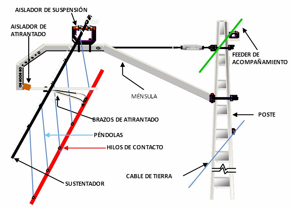
What we call “Messenger Wire” is the one forming the catenary curve on which is suspended the contact-wire attached by the “droppers” of different length to keep the contact-wire horizontal.


Parts composing the Catenary System

Catenary type

In the railway, we can find different types of catenary according to the importance of the railway on which they are installed. Thus, we have:

  • General-railway catenary and main station-railway, composed of: 
    • Messenger copper-wire of 153 mm2 
    • 2 contact-wires of copper of 107 mm2 
  • Secondary station-railway: 
    • Messenger steel-wire of 42 mm2 
    • 1 contact-wire of copper of 107 mm2 
  • Trolley or tramway: 
    • 1 contact-wire of copper of 107 mm2 

Other kind of catenary is the “rigid catenary”, used mainly in subways. This kind of catenary consists of a rigid aluminum profile with the contact wire embedded. They need very low loading gauge for the installation.

Compensated catenary

The cables composing the catenary (messenger and contact wires) are subject to length variations due to the thermal-dilatation caused by the temperature changes. When the length of the cable changes, the geometry of the catenary changes as well, changing the sag of the cables.

This effect is undesirable for the picking-quality of the pantograph, and this is why special devices for the automatic regulation of the mechanical tension.  

Counterweight compensation in a general railway. 

Spring-compensation used with tramways. The spring can also be installed within a hollow mast.

GO TO CHAPTER IX- Railway Loading Gauges

Full themes in the book -In paper and ebook-(Follow the link)


------------------------------------------------------------------

La Catenaria

Se llama catenaria a la curva que hace un cable suspendido entre dos puntos fijos, situados a la misma altura
En el ferrocarril, llamamos catenaria al conjunto de elementos que forman la línea aérea de contacto (LAC), de la que se alimentan los trenes eléctricos a través del pantógrafo. 
Lo que llamamos cable sustentador,es el que forma la curva catenaria y es de la que cuelga el hilo de contacto sujeto por las péndolas.

Partes que componen el sistema de la catenaria

Tipos de catenaria

En el ferrocarril, distinguimos los distintos tipos de catenaria en función de la importancia de la vía sobre la que se sitúe. Así tenemos:
  • Catenaria de vía general y vía principal de estación formada por :
    • Sustentador de cobre de                                   153 mm2
    • Dos hilos de contacto de cobre de 107 mm2 =  214 mm2
  • Vía secundaria de estación:
    • Sustentador de acero de                                     42 mm2
    • Un hilo de contacto de cobre de                         107 mm2
  • Troley o tranviario:
    • Un hilo de contacto de cobre de                         107 mm2
Otro tipo de catenaria es la catenaria rígida, utilizada especialmente en metros. Está formada por un perfil rígido de aluminio que lleva incrustado el hilo de contacto. Necesitan de muy poco gálibo para su instalación.


Catenaria compensada

Los cables conductores que forman la catenaria (sustentador e hilo[s] de contacto) se ven sujetos a variaciones de longitud debidas a la dilatación térmica producida por los cambios de temperatura. Al variar la longitud de los cables, la geometría de la catenaria se modifica, variando la flecha de los cables.

Este efecto es indeseable para la calidad de captación del pantógrafo, por lo cual se instalan elementos de regulación automática de la tensión mecánica.


Compensación por contrapesos en vía general
Compensación por muelles utilizada en tranvías.
El muelle puede ir embebido en algún poste

IR A CAPÍTULO IX - Gálibos Ferroviarios

Temas completos en el libro - en papel y ebook (Siga este enlace)