The first constant we need to know in order to design a railway route is
the width of straight railway, “a”:

The railway width is the distance between the two inner faces of each
rails, also called “active faces”. It is measured between 10 and 15mm below the
rolling-plane, depending on the rail-type and its tilt.

For some calculations, as is the case of the camber, the parameter “S” is
used, which is the distance between the axis of the rails, so we must know the
rail-type with which we are going to work in order to add the width of the
rail-head to the railway-width: S=a+c

nother essential datum to be considered for the calculations is the
maximum speed expected for the train circulating, “Vmax”.
Depending on the kind of vehicle circulating (travelers, merchandise, or both),
the circulation speed will be different and therefore so will be the loads on
the rails.
Since the camber “H“ is
directly related with speed, it will also dependent on the circulation type.
Another parameter to be considered in order to set the maximum camber is
the overturning torque that can produce a vehicle stopped or moving at a low
speed on the lower or inner rail in a curve.
In this way, it must be always avoided that the fastener of the rail to the
sleeper or the concrete-slab work on traction (see below):
Considering
together all the parameters abovementioned, we can set the right maximum camber
( “Hmax”). This
datum is in principle provided by the Administration in charge of the route.
Thus, for:
a=
1.435 mm Hmax = 145 mm
a= 1.668 mm Hmax
= 160 mm
a= 1.000 mm Hmax = between 100 and 120 mm
a= 1.000 mm Hmax = between 100 and 120 mm
We
can know that the rail is placed in the railway with a tilt of 1/20 inwards.

The
camber reduces the tilt in the inner rail of a curve, even getting vertical
when H=s/20.

Beyond this limit, the rail will tilt
outwards.
Aiming to limit this tilt, several authors suggest that the camber must not exceed the 1/10 of the railway-width.
Hmax<= s/10
In international width (s=1.507 mm)*
H<=151
mm
In Iberian width (s=1.740 mm)* H<=174 mm
In metrical width (s=1.072 mm)* H<=107mm
In Iberian width (s=1.740 mm)* H<=174 mm
In metrical width (s=1.072 mm)* H<=107mm
* (s= railway-width between axis with rail type UIC54)
For a maximum camber (Hmax) and a maximum speed (Vmax )
a minimum radius will correspond (Rmin).
As we will prove later:
Rmin=(s* Vmax 2 )/ ((Hmax+I)*127)
In some routes, as is the case of the tramways, it has to be very
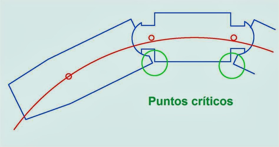
considered also the inscription of the very vehicle in the curve:
Inscription of the wheels in the railway “box”.


Inscription of the train-convoy into the curve.

This is way, when it comes to project a route or tracing, the Administration
must confirm us first the minimum radius of the curve.
GO TO CHAPTER IV - Tracing of the Railroad
Full themes in the book -In paper and ebook-(Follow the link)
Constantes.-
La primera constante que necesitamos conocer para diseñar un trazado ferroviario es el ancho de vía en recta , “a”
El ancho de vía es la distancia entre las caras internas del carril, llamadas también caras activas. Se mide entre 10 a 15 mm por debajo del plano de rodadura, dependiendo del tipo de carril y de la inclinación de este.
Para algunos cálculos, como es el caso del peralte se utiliza la distancia “S” entre ejes de los carriles, por lo que deberemos conocer el tipo de carril con el que se va a trabajar para sumar al ancho de vía el ancho de una cabeza de carril.
Otro dato imprescindible será la velocidad máxima a la va a circular el tren, “V max”
Dependiendo del tipo de vehículo que vaya a circular, viajeros, mercancías o los dos, las velocidades a las que circulen serán distintas, y por lo tanto las fuerzas que actúan en los carriles también serán distintas.
Como el peralte “ H “ está directamente relacionado con la velocidad, este dependerá también del tipo de circulación.
Otro dato que hay que tener en cuenta para establecer un peralte máximo, es el par de vuelco que puede producir un vehículo parado o a poca velocidad sobre el carril inferior de una curva.
Hay que evitar siempre que la fijación del carril a la traviesa o a la losa de hormigón trabaje a tracción.
El conjunto de estas consideraciones nos indicará un peralte máximo conveniente “Hmax”. Este dato nos lo facilitará cada administración, así para:ADIF - Ancho a= 1.668 mm Hmax = 160 mm
ADIF – AVE a= 1.435 mm Hmax = 145 mm
ADIF – FEVE a= 1.000 mm Hmax = 110 mm
EuskoTren a= 1.000 mm Hmax = 100 mm
Sabemos que el carril se coloca en la vía con una inclinación hacia el interior de 1/20.
El peralte reduce esta inclinación en el carril interior, que llega a ponerse vertical cuando: H=s/20
Mas allá de este límite, el carril se inclina hacia el exterior de la vía.
Con el fin de limitar esta inclinación, diversos autores establecen que el peralte no de debe sobrepasar el 1/10 del ancho de vía.
Hmax<= s/10
Con el fin de limitar esta inclinación, diversos autores establecen que el peralte no de debe sobrepasar el 1/10 del ancho de vía.
Hmax<= s/10
–En ancho ibérico (s=1.740 mm)* H<=174 mm ; Adif =160
–En ancho internacional (s=1.507 mm)* H<=151 mm ; Adif =145
–En ancho métrico (s=1.072 mm)* H<=107mm ; Feve=110, EuskoTren=100; MetroBilbao=120
*( s= Ancho de vía entre ejes de carril con carril UIC54)
Según este estudio, ADIF cumpliría en 2 anchos, Feve estaría en límite y cumpliría EuskoTren, pero no cumpliría Metro Bilbao.
Para un peralte máximo ( Hmax ) y una velocidad máxima ( Vmax ) le corresponderá un radio mínimo (Rmin ).
(Como demostraremos más adelante) Rmin = ( s x ( Vmax ) 2 ) / (( Hmax + I ) x 127)
Pero no solamente influye esto, sino que a veces, sobre todo en tranvías, hay que tener muy en cuenta la inscripción del propio vehículo en la curva.
- Inscripción de las ruedas en la caja de la vía
- Inscripción del convoy en la curva
Por esto motivos, a la hora de proyectar un trazado, el radio mínimo de la curva es un dato que nos lo deberá confirmar la administración.
IR A CAPÍTULO IV - Trazado de una Vía Férrea
Temas completos en el libro - en papel y ebook (Siga este enlace)


No hay comentarios:
Publicar un comentario